The type of flange to be used for a piping application depends, mainly, on the required strength for the flanged joint. Flanges are used, alternatively to welded connections, to facilitate maintenance operations (a flanged joint can be dismantled quickly and conveniently).
Let’s now dive in, showing the key types of flanges with pictures.
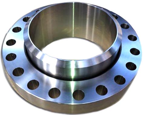
WELDING NECK FLANGE
.
A welding neck flange (“WN”)features a long tapered hub that can be welded with a pipe.
This flange type is used, normally, in high-pressure and high/low temperatures applications that require an unrestricted flow of the fluid conveyed by the piping system (the bore of the flange matches with the bore of the pipe).
The absence of pressure drops prevents negative effects as turbulence and erosion/corrosion of the metals in the proximity of the flanged joints.
The tapered hub allows a smooth distribution of the mechanical stress between the pipe and the weld neck flange and facilitates the execution of radiographic inspections to detect possible leakages and welding defects.
The dimension of the flange (NPS and the pipe schedule) shall match the dimension of the connecting pipe.
A welding neck flange is connected to a pipe by a single full penetration V-shaped butt weld. The dimension and weights of ASME weld neck flanges are shown in this article.
LONG WELDING NECK
Long weld neck flanges (“LWN”) are similar to weld neck flanges, with the exception that the neck (tapered hub) is extended and acts like a boring extension.
Long weld neck flanges are generally used on vessels, columns or barrels. These flange types are available also in the heavy barrel (HB) and equal barrel (E) types.
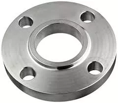
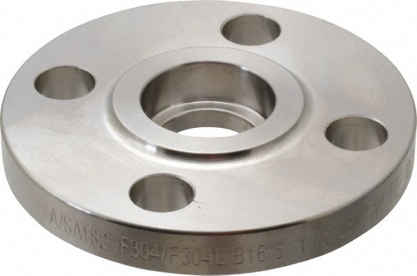
SLIP ON FLANGE
A slip-on flange is connected to the pipe or the fittings by two fillet welds, one executed inside and one outside the cavity of the flange.
The bore size of a slip-on flange is larger than the outside diameter of the connecting pipe, as the pipe has to slide inside the flange to be connected by the execution of a fillet weld.
Slip-on flanges are also defined “Hubbed Flanges” and they are easy to recognize due to their slim and compact shape.
The dimensions and weights of slip-on flanges ANSI/ASME are available on this page.
WELD NECK VS SLIP ON FLANGE
Flanged joints made with slip-on flanges are, in the long run, a bit more fragile than connections made with welding neck flanges (in similar service conditions). This seems due to the following facts:
a welding neck flange features a tapered hub, absent in a socket weld flange, which distributes the mechanical stress between the pipe and the flange more evenly
a welding neck joint as only one welding area instead of two (socket weld flange).
Another advantage of the welding neck flange is that it can be connected either to pipes and fittings, whereas socket weld flanges suit pipes only.
THREADED FLANGE
Threaded flanges are joined to pipes by screwing the pipe (which has a male thread, generally NPT per ASME B1.20.1) onto the flange, without seam welds (in certain cases, though, small welds are applied to increase the strength of the connection).
Threaded flanges are available in sizes up to 4 inches and multiple pressure ratings, however, they are used, mostly, small size piping in low pressure and low-temperature applications, like water and air utility services.
Threaded flanges are also a mandatory requirement in explosive areas, such as gas stations and plants, as the execution of welded connections in such environments would be dangerous.
Consult this article, to find about the dimension of ANSI/ASME threaded flanges.
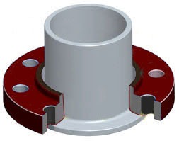
SOCKET WELD FLANGE
.
Socket weld flanges are connected to pipes using a single fillet weld executed on the outer side of the flange (different from the slip-on flange type that requires two welds).
According to ASME B31.1, to execute a flanged connection using a socket weld flange, the pipe shall be at first inserted in the socket of the flange until it reaches the bottom of the flange, then it should be lifted by 1.6 mm and finally welded.
This gap shall be left to allow proper positioning of the pipe inside the flange socket after the solidification of the weld.
Socket Weld Flanges are used for small-size and high-pressure piping that do not transfer highly corrosive fluids.
This due to the fact that these flange types are subject to corrosion in the gap area between the end of the pipe and the shoulder of the socket.
Their static strength of socket weld flanges is similar to slip-on flanges’, but their fatigue strength is higher due to the presence of a single, instead of double, fillet weld.
Sizes and weights of socket-weld flanges (ASME/ANSI) are reported here.
LAP JOINT FLANGE
Lap joint flanges feature a flat face and are always used in conjunction with a stub end.
Lap joint flanges resemble, in shape, slip-on flanges except for the radius at the crossing of the flange face and the bore to accommodate the flanged portion of the stub end.
A lap joint flange slips over the pipe and seats on the back of the stub end and the two are kept together by the pressure of the bolts.
The use of lap joint flanges in combination with stub ends is a cost-effective solution for stainless steel or nickel alloy pipelines, as the material of the lap joint flange can be of a lower grade (generally carbon steel) than the material of the stub end (which has to match the pipe grade, as in contact with the conveyed fluid).
This arrangement, therefore, has these two advantages:
reduces the overall cost of the pipeline’s flanged joints, as the use of higher grade materials is minimized;
bolting operations are simplified, as the lap joint flange can be rotated around the pipe to help with bolts alignment.
The dimensions and weights of lap joint flanges are shown in this article.
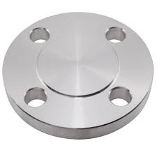
BLIND FLANGE
Contrary to all the flange types seen above, blind flanges do not have a center hole, and are used to blind or seal a pipeline, a valve/pressure vessel and block the flow of the fluid.
Blind flanges have to withstand remarkable mechanical stress due to the system pressure and the required bolting forces.
Blind flanges allow easy access to the pipeline, as they can be easily unbolted to let the operator execute activities inside the terminal end of the pipe (this is also the reason why the blind flange type is used as manhole for pressure vessels, at times).
It is maybe interesting to observe that, while this flanges type is easier to manufacture, they are sold at a premium average cost per kilogram compared to the other flange types.
Refer to this article to learn about the dimensions of blind flanges per ANSI/ASME B16.5.
SPECIAL TYPES OF FLANGES
NIPOFLANGE
Nipoflange
A Nipoflange is used for branch pipelines at 90 degrees and is a product manufactured by combining a welding neck flange with a forged Nipolet.
However, a Nipoflange is a solid single piece of forged steel and not two different products welded together.
To install a Nipoflange, the piping staff has to weld the Nipolet part of the device on the run pipe and bolt the flanged part on the flange of the branched pipe.
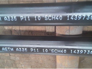
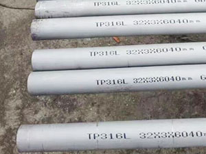
Nipoflanges are available in different materials, such as carbon steel ASTM A105 (high-temperature service), ASTM A350 (low-temperature carbon steel), ASTM A182 (stainless steel grades, including duplex and super duplex) and nickel alloys (Inconel, Incoloy, Hastelloy, etc).
Nipoflanges are also manufactured in the reinforced variant, which has additional mechanical strength compared to a standard Nipoflange.
WELDOFLANGE
Weldoflange
A Weldoflange is conceptually similar to a Nipoflange, as that they are a combination of a weld neck flange and a branch fitting connection (a Weldolet in this case). Weldoflanges are made out of a single piece of solid forged steel, not by welding separate parts together.
ELBOFLANGE AND LATROFLANGE
Other less common types of flange Olets is the so-called Elboflange (a combination of a flange and an Elbolet) and “Latroflange” (combination of a flange with a Latrolet). Elboflanges are used to branch a pipeline at 45 degrees.
Elboflange
SWIVEL FLANGE
Swivel ring flanges facilitate the alignment of the bolt holes between the two mating flanges, a feature that is helpful in many circumstances, such as the installation of large diameter pipelines, subsea and offshore pipelines, pipe works in shallow waters and similar environments.Swivel flanges suit oil, gas, hydrocarbons, water, chemical and other demanding fluids in petrochemical and water management applications.
In the case of a large diameter pipeline, for instance, the pipe is fitted, at one end, with a standard welding neck flange, and with a swivel flange at the other end: by simply rotating the swivel flange on the pipe, the operators can achieve a perfect alignment of the bolt holes in a way easier and faster way.
The major standards for swivel ring flanges are ASME/ANSI, DIN, BS, EN, ISO, etc. The most common standard for petrochemical application is the ANSI/ASME B16.5 or ASME B16.47.
Swivel flange
Swivel flanges are available in all the standard shapes of common flanges, i.e. weld-neck, slip-on, lap-joint, socket weld etc, in all material grades and in a wide dimensional range (sizes can vary from 3/8” to 60” and pressure rating from 150 to 2500).
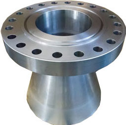
Expanding flanges, or “expander flanges”, are used to increase the bore of the pipeline from a specific point to another or to connect pipes to other mechanical devices such as pumps, compressors, and valves that have different inlets sizes.
The expanding flange represented in the picture is a welding neck flange with a larger bore on the non-flanged end.
Expanding flanges can be used to increase the run pipe bore only by one or maximum two sizes and not more (example: from 2 to 3 or maximum 4 inches).
Expander flanges are a cheaper (and lighter) solution compared to the combination of a buttweld reducer and a standard flange (which is the standard solution for pipe bore increases above 2 sizes).
The most common materials for expanding flanges are A105 (high-temp. carbon steel), A350 (LTCS) and ASTM A182 (stainless steel and above).
Pressure ratings and dimensions of expanding flanges are in accordance with the ANSI/ASME B16.5 specification and are available with raised or flat face (RF, FF).
The drawing of an ASME expanding flange.
REDUCING FLANGE (“REDUCER”)
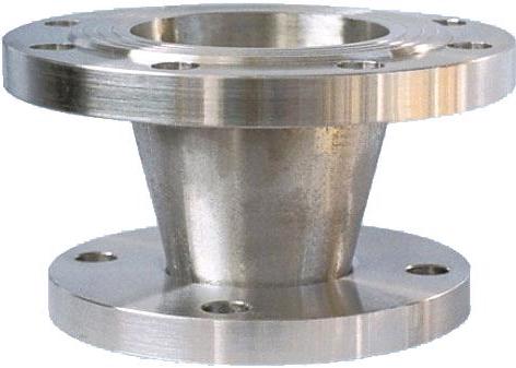
Reducer flange
Reducing flanges, otherwise called reducer flanges, have an opposite function than expander flanges seen above, i.e. they are used to decrease the bore of a pipeline.
The bore of the run pipe can be safely reduced by only 1 or 2 sizes (otherwise a solution based on the combination of a butt weld reducer and a standard flange has to be used).
Reducing flanges are available in most sizes and material grades, and are not generally available from stock.
Reducing flanges follow the same considerations in terms of specifications, sizes and material grades as expander flanges.

 .
. 


 .
.