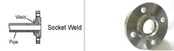
Socket Weld (SW) flanges are a category of weld neck flanges with a socket (recessed bore) that accepts the plain end of a pipe. The pipe is inserted into the socket and fillet-welded around the outside — providing a strong, leak-resistant joint with no bore obstruction. Socket Weld flanges are most commonly used in small-bore piping systems (NPS ½″ to NPS 4″) for oil & gas, chemical, and general industrial applications.
Per ASME B16.5-2022, Socket Weld flanges are available in Class 150, 300, 600, 900, 1500, and 2500 for sizes NPS ½″ through NPS 3″ (and up to NPS 4″ for certain pressure classes). They are typically supplied with a Raised Face (RF) as standard, though flat face and RTJ options are available.
HT PIPE supplies Socket Weld flanges in carbon steel, stainless steel, alloy steel, and nickel alloys, with full material test reports (MTR / EN 10204 3.1) and third-party inspection available on request.
Socket Weld Flange — Dimension Parameters
| Symbol |
Parameter |
Description |
| NPS |
Nominal Pipe Size |
Nominal pipe size in inches (1/2 to 4 in.) |
| O |
Outside Diameter |
Overall flange diameter |
| C |
Hub Thickness |
Minimum hub thickness at the weld joint (raised face adds ~1.6 mm) |
| H |
Hub Outside Diameter |
Outside diameter of the hub at the weld end |
| W |
Bolt Circle Diameter |
Center-to-center diameter of bolt holes |
| dh |
Bolt Hole Diameter |
Diameter of each bolt hole (bolt diameter + ~3 mm clearance) |
| n |
Number of Bolts |
Total bolt count — always an even number |
| B |
Pipe Bore Diameter |
Approximate inside diameter of the matching pipe (nominal bore) |
| Weight |
Est. Carbon Steel Mass |
Estimated weight in kilograms for carbon steel SW flange |
Class 150 Socket Weld Flange Dimensions ASME B16.5
NPS
(in) |
B
Bore (mm) |
O
OD (mm) |
C
Thick. (mm) |
H
Hub OD (mm) |
W
BC (mm) |
dh
(mm) |
n |
Weight
(kg, CS) |
| 1/2 |
21.3 |
89.0 |
11.1 |
30.2 |
60.3 |
15.9 |
4 |
0.9 |
| 3/4 |
26.7 |
98.4 |
11.1 |
38.1 |
69.9 |
15.9 |
4 |
0.9 |
| 1 |
33.4 |
108.0 |
12.7 |
46.0 |
79.4 |
15.9 |
4 |
0.9 |
| 1-1/4 |
42.2 |
117.5 |
14.3 |
54.1 |
88.9 |
15.9 |
4 |
1.4 |
| 1-1/2 |
48.3 |
127.0 |
15.9 |
61.9 |
98.4 |
15.9 |
4 |
1.4 |
| 2 |
60.3 |
152.4 |
17.5 |
77.9 |
120.7 |
19.1 |
4 |
2.3 |
| 2-1/2 |
76.1 |
177.8 |
20.7 |
91.9 |
139.7 |
19.1 |
4 |
3.6 |
| 3 |
88.9 |
190.5 |
22.3 |
108.0 |
152.4 |
19.1 |
4 |
4.1 |
| 4 |
114.3 |
228.6 |
22.3 |
132.5 |
190.5 |
19.1 |
8 |
5.9 |
Class 300 Socket Weld Flange Dimensions ASME B16.5
NPS
(in) |
B
Bore (mm) |
O
OD (mm) |
C
Thick. (mm) |
H
Hub OD (mm) |
W
BC (mm) |
dh
(mm) |
n |
Weight
(kg, CS) |
| 1/2 |
21.3 |
95.3 |
22.3 |
34.9 |
66.7 |
15.9 |
4 |
1.4 |
| 3/4 |
26.7 |
117.5 |
25.4 |
42.9 |
82.6 |
19.1 |
4 |
1.4 |
| 1 |
33.4 |
124.0 |
26.9 |
50.8 |
88.9 |
19.1 |
4 |
1.4 |
| 1-1/4 |
42.2 |
133.4 |
26.9 |
63.5 |
98.4 |
19.1 |
4 |
1.8 |
| 1-1/2 |
48.3 |
155.6 |
30.2 |
73.0 |
114.3 |
22.2 |
4 |
2.7 |
| 2 |
60.3 |
165.1 |
33.3 |
92.1 |
127.0 |
19.1 |
8 |
3.2 |
| 2-1/2 |
76.1 |
190.5 |
38.1 |
104.8 |
149.2 |
22.2 |
8 |
4.5 |
| 3 |
88.9 |
209.6 |
42.9 |
127.0 |
168.3 |
22.2 |
8 |
5.9 |
| 4 |
114.3 |
254.0 |
47.8 |
158.8 |
200.0 |
22.2 |
8 |
9.9 |
Class 600 Socket Weld Flange Dimensions ASME B16.5
Note: Class 400 Socket Weld flanges for NPS ½″ to NPS 2½″ may be supplied using Class 600 dimensions per ASME B16.5 Clause 6.3. Class 600 is the standard offering for these sizes.
NPS
(in) |
B
Bore (mm) |
O
OD (mm) |
C
Thick. (mm) |
H
Hub OD (mm) |
W
BC (mm) |
dh
(mm) |
n |
Weight
(kg, CS) |
| 1/2 |
21.3 |
95.3 |
28.7 |
34.9 |
66.7 |
15.9 |
4 |
0.9 |
| 3/4 |
26.7 |
117.5 |
31.8 |
42.9 |
82.6 |
19.1 |
4 |
1.4 |
| 1 |
33.4 |
124.0 |
33.3 |
50.8 |
88.9 |
19.1 |
4 |
1.8 |
| 1-1/4 |
42.2 |
133.4 |
34.9 |
63.5 |
98.4 |
19.1 |
4 |
2.3 |
| 1-1/2 |
48.3 |
155.6 |
38.1 |
73.0 |
114.3 |
22.2 |
4 |
3.2 |
| 2 |
60.3 |
165.1 |
42.9 |
92.1 |
127.0 |
19.1 |
8 |
4.1 |
| 2-1/2 |
76.1 |
190.5 |
47.8 |
104.8 |
149.2 |
22.2 |
8 |
5.9 |
| 3 |
88.9 |
209.6 |
52.4 |
127.0 |
168.3 |
22.2 |
8 |
7.2 |
| 4 |
114.3 |
273.1 |
62.0 |
165.1 |
215.9 |
25.4 |
8 |
16.7 |
Class 1500 Socket Weld Flange Dimensions ASME B16.5
Note: Class 1500 Socket Weld flanges are available for NPS ½″ through NPS 2½″ per ASME B16.5. NPS 3 and above are not standard in Class 1500 socket weld — refer to Weld Neck flanges for those size/pressure combinations.
NPS
(in) |
B
Bore (mm) |
O
OD (mm) |
C
Thick. (mm) |
H
Hub OD (mm) |
W
BC (mm) |
dh
(mm) |
n |
Weight
(kg, CS) |
| 1/2 |
21.3 |
120.7 |
38.1 |
34.9 |
82.6 |
22.2 |
4 |
2.7 |
| 3/4 |
26.7 |
130.2 |
41.4 |
42.9 |
88.9 |
22.2 |
4 |
2.7 |
| 1 |
33.4 |
149.4 |
47.8 |
50.8 |
101.6 |
25.4 |
4 |
3.6 |
| 1-1/4 |
42.2 |
158.8 |
47.8 |
63.5 |
111.1 |
25.4 |
4 |
4.5 |
| 1-1/2 |
48.3 |
177.8 |
50.8 |
73.0 |
123.8 |
28.6 |
4 |
6.3 |
| 2 |
60.3 |
215.9 |
63.5 |
92.1 |
165.1 |
25.4 |
8 |
11.3 |
| 2-1/2 |
76.1 |
244.6 |
69.9 |
104.8 |
190.5 |
28.6 |
8 |
16.2 |
Pressure Class Quick Reference
| Class |
Max NPS (SW) |
Typical Application |
| Class 150 |
NPS 1/2 – 4 |
General utility, water, air, low-pressure process |
| Class 300 |
NPS 1/2 – 4 |
Higher pressure, temperature, oil & gas process |
| Class 600 |
NPS 1/2 – 4 |
High-pressure oil & gas, chemical, refinery |
| Class 900 |
NPS 1/2 – 2-1/2 |
Very high pressure, limited by size availability |
| Class 1500 |
NPS 1/2 – 2-1/2 |
Critical high-pressure, sour gas, high-temp service |
Dimension Tolerances (ASME B16.5)
| Dimension |
Tolerance (NPS ≤ 24) |
Notes |
| Outside Diameter (O) |
±1.6 mm |
Applies to all pressure classes |
| Hub Thickness (C) |
+3.2 mm / −0 mm |
NPS ≤ 18; larger tolerance for NPS ≥ 20 |
| Bolt Circle (W) |
±1.6 mm |
Also applies to bolt hole eccentricity |
| Hub OD (H) |
+3.2 mm / −0.8 mm |
Per ASME B16.5 Table 7 |
| Length Through Hub |
+3.2 mm / −0.8 mm |
NPS ≤ 18 |
| Bore (B) |
±0.8 mm (small NPS)
+1.6 mm / −0 mm (large NPS) |
Tolerance tightens for smaller sizes |
Reference Standard: ASME B16.5-2022 — Pipe Flanges and Flanged Fittings, NPS ½ Through NPS 24. Published by ASME International. © ASME.
Disclaimer: Dimensions shown are for reference only. Verify against the current edition of ASME B16.5 and applicable project specifications before design or procurement. HT PIPE assumes no liability for the use of this data.