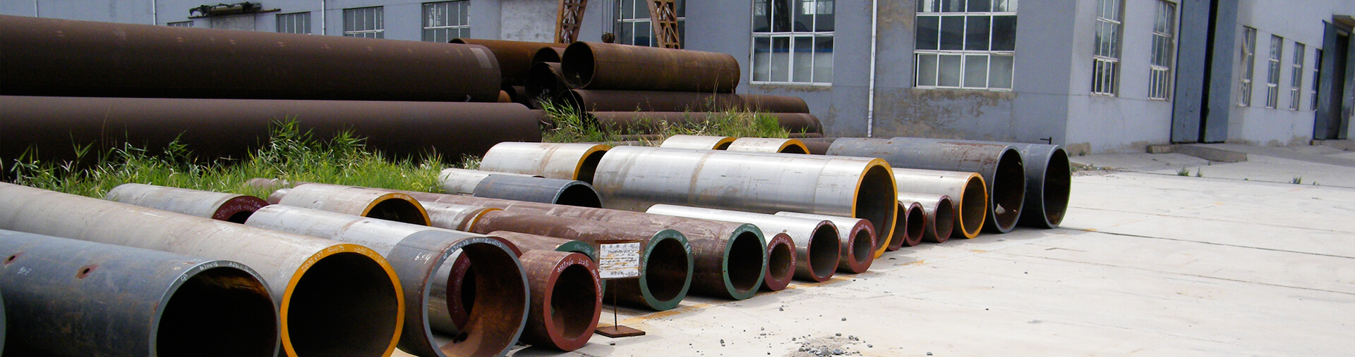
1. Scope
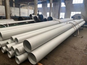
This standard covers factory-made wrought buttwelding fittings in all materials — carbon steel, alloy steel, stainless steel, and nickel alloy — in sizes NPS 1/2 through NPS 48. ASME B16.9 is a dimensional manufacturing standard; it defines the geometry, tolerances, and marking requirements. The fitting material is specified separately per the applicable material specification (ASTM A234, A403, A815, A860, B366, etc.). The same dimensions apply regardless of the material used.
- Elbows: 90° and 45°, long radius (LR = 1.5D) and short radius (SR = 1.0D)
- Tees: equal and reducing
- Reducers: concentric and eccentric
- Caps: buttweld caps
- Returns: 180° returns, long radius only
Edition: ASME B16.9-2024 | Governing Code: ASME Boiler and Pressure Vessel Code (BPVC), Section II | Nature: Dimensional manufacturing standard — applies to all butt-welding fitting materials listed in the applicable piping code | Common Material Specs: ASTM A234 (carbon/alloy), A403 (stainless), A815 (duplex/ferritic SS), A860 (high-strength), B366 (nickel alloy), A420 (low-temp carbon steel)
2. Fitting Types and Dimensional Standards
2.1 90° Elbow — Center-to-End Dimension (A)
| NPS |
DN |
Long Radius (1.5D) A = 1.5 × OD (mm) |
Short Radius (1.0D) A (mm) |
| 1/2 |
15 |
38 |
— |
| 3/4 |
20 |
57 |
— |
| 1 |
25 |
76 |
51 |
| 1-1/2 |
40 |
114 |
76 |
| 2 |
50 |
152 |
102 |
| 3 |
80 |
229 |
152 |
| 4 |
100 |
305 |
203 |
| 6 |
150 |
457 |
305 |
| 8 |
200 |
610 |
406 |
| 10 |
250 |
762 |
508 |
| 12 |
300 |
914 |
610 |
| 16 |
400 |
1219 |
813 |
| 20 |
500 |
1524 |
1016 |
| 24 |
600 |
1829 |
N/A (use B16.28) |
2.2 Equal Tees — Center-to-End Dimensions (Outlets)
| NPS |
DN |
Run C = Run Center-to-End (mm) |
Branch M = Branch Center-to-End (mm) |
| 1 |
25 |
102 |
102 |
| 2 |
50 |
152 |
152 |
| 4 |
100 |
305 |
305 |
| 6 |
150 |
457 |
457 |
| 8 |
200 |
610 |
610 |
| 10 |
250 |
762 |
762 |
| 12 |
300 |
914 |
914 |
| 16 |
400 |
1219 |
1219 |
| 24 |
600 |
1829 |
1829 |
2.3 Concentric and Eccentric Reducers — Overall Length (L)
| Larger NPS |
Smaller NPS |
Overall Length L (mm) |
| 2 |
1 |
152 |
| 4 |
2 |
305 |
| 6 |
4 |
457 |
| 8 |
6 |
610 |
| 10 |
6 |
610 |
| 12 |
8 |
610 |
| 16 |
12 |
610 |
| 20 |
16 |
610 |
| 24 |
18 |
610 |
3. Pipe Schedule to Fitting End-Wall Thickness
ASME B16.9 fittings match the end-wall thickness of the corresponding pipe schedule. The centre body of the fitting may be thicker than the end, providing inherent strength above the pipe schedule.
| NPS Range |
Available Schedules |
Designation Method |
| NPS 1/2 – 10 |
STD (Sch 40), XS (Sch 80) |
Weight designation (STD/XS) |
| NPS 12 and above |
Sch 10, 20, 30, 40, 60, 80, 100, 120, 140, 160 |
Schedule number |
4. End Preparation (Beveling)
| Parameter |
Requirement |
| Bevel angle |
30° +0°/−5° from pipe axis |
| Tolerance land (land face) |
1.6 mm ±0.8 mm (1/16 in ±1/32 in) |
| Internal diameter at end |
Matches nominal bore of corresponding pipe schedule |
| End squareness tolerance |
0.06 mm per mm of diameter (max) |
| NPS ≥ 24 bevel type |
Standard bevel; compound bevel optional |
5. Tolerances (Summary)
| Dimensional Parameter |
Tolerance |
| Center-to-end A, C, M (NPS ≤ 12) |
±1.5 mm |
| Center-to-end A, C, M (NPS > 12) |
±3.0 mm |
| Overall length H (NPS ≤ 12) |
±1.5 mm |
| Overall length H (NPS > 12) |
±3.0 mm |
| Outside diameter at bevel |
±1% of OD (min 0.8 mm) |
| Wall thickness at ends |
No thinner than specified minimum; no more than 1.14 × specified min |
| Angularity of end preparation |
Per bevel dimension drawing |
6. Pressure–Temperature Ratings
ASME B16.9 fittings do not have independent pressure-temperature ratings. Their rating is established by the matching pipe and flange pressure-temperature ratings per ASME B16.5 (for flange connections) or the applicable pipe specification. Key principles:
- Fittings rated at the same pressure class as the connecting pipe (e.g., a WPB fitting on a Schedule 40 pipe carries the same pressure-temperature rating as the pipe)
- For flange-type end connections, the fitting's pressure-temperature rating equals the matching ASME B16.5 Class rating
- Hydrostatic test pressure: 1.5× the design pressure at ambient temperature (minimum)
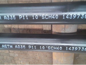
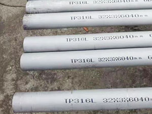
7. Marking Requirements
| Marking Element |
Example |
| Manufacturer's name or trademark |
HT PIPE |
| Material designation |
WPB (per ASME SA-234) |
| Size (NPS) |
4 |
| Schedule or weight |
STD or Sch 40 |
| B16.9 compliance marking |
B16.9 |
| Heat number or batch trace |
Heat No. / Batch No. |
8. Comparison with Related Buttweld Fitting Standards
| Standard |
Size Range |
Material |
Key Distinction |
| ASME B16.9 |
NPS 1/2 – 48 |
All materials |
General-purpose LR/SR elbows, tees, reducers, caps; dimensional standard for all butt-weld fittings |
| ASME B16.28 |
NPS 1/2 – 24 |
All materials |
SR 90-degree elbows (1.0D), SR returns — supplements B16.9 for SR fittings NPS greater than 10 |
| ASME B16.49 |
NPS 4 – 48 |
All materials |
Induction-bent pipe (continuous arc) for pipeline transport (B31.3/B31.4/B31.8); not a discrete fitting |
| MSS SP-43 |
NPS 1/2 – 48 |
Stainless steel only |
Simplified B16.9 for stainless steel; schedules 10S and 40S per ASME B36.19M |
| MSS SP-75 |
NPS 1 – 24 |
High-strength ferritic steel only |
WPHY 42–70; X42–X70 yield strengths; pipeline fittings per B31.4/B31.8 |
9. Related Standards
| Standard |
Title |
| ASME B16.5 |
Pipe Flanges and Flanged Fittings (for pressure-temperature ratings) |
| ASME B16.25 |
Buttwelding Ends (bevel and end preparation) |
| ASME B16.28 |
Wrought Steel Buttwelding Short Radius Elbows and Returns |
| ASME B16.49 |
Factory-Made Wrought Steel Buttwelding Induction Bends |
| ASME SA-234 |
Pipe Fittings of Wrought Carbon Steel and Alloy Steel (material spec) |
| ASME SA-403 |
Wrought Austenitic Stainless Steel Piping Fittings (stainless material spec) |
| ASME SA-860 |
Wrought High-Strength Ferritic Steel Fittings (MSS SP-75 material spec) |
| ASME B36.10M |
Welded and Seamless Wrought Steel Pipe (schedule dimensions) |
| MSS SP-25 |
Standard Marking System for Valves, Fittings, Flanges and Unions |
| MSS SP-43 |
Wrought Stainless Steel Buttwelding Fittings (stainless simplification) |
| MSS SP-75 |
Wrought High-Strength Ferritic Steel Buttwelding Fittings |
10. How to Order (Per ASME B16.9)
| Order Element |
Specification |
Example |
| Standard |
ASME B16.9 |
B16.9 |
| Fitting type |
Elbow/Tee/Reducer/Cap/Return |
Elbow |
| Radius |
LR (1.5D) / SR (1.0D) |
LR |
| Size |
NPS |
6 |
| Schedule / Weight |
Schedule number or STD/XS |
STD |
| Material grade |
Per purchase order (SA-234 WPB etc.) |
WPB |
| Ends |
Beveled (standard) / Threaded (if permitted) |
Beveled |
| Quantity |
Number of pieces |
20 |
| Pressure test requirement |
Hydrostatic test pressure if required |
Per B16.9 |
| Third-party inspection |
EN 10204 3.1 MTC if required |
3.1 MTC |
11. FAQ — Frequently Asked Questions
| Question |
Answer |
| What is the maximum size for SR (1.0D) elbows in ASME B16.9? |
SR elbows per B16.9 are available up to NPS 22. For NPS 24 and larger, SR elbows must be specified per ASME B16.28. B16.28 covers SR 90° elbows from NPS 1/2 to NPS 24 and SR return bends from NPS 1/2 to NPS 12. |
| Can B16.9 fittings be used with stainless steel pipe? |
Yes. Dimensionally, ASME B16.9 governs stainless steel buttweld fittings; the material must comply with ASTM A403 (for austenitic/duplex stainless) or ASTM A815 (for ferritic/duplex stainless). The fitting dimensions (C, M, H) are identical to carbon steel B16.9 regardless of material. The matching pipe is typically ASTM A312. |
| Are MSS SP-75 fittings dimensionally interchangeable with ASME B16.9? |
No. MSS SP-75 has its own dimensional tables — fittings are not dimensionally identical to B16.9. SP-75 covers WPHY 42–70 materials for high-strength pipeline applications (ASME B31.4/B31.8). SP-75 fittings are shorter (L dimensions ~50–75% of B16.9) to reduce weight in pipeline service. Always specify the correct standard on the purchase order. |
| What is the difference between concentric and eccentric reducers? |
Concentric reducers maintain a constant centreline axis — the bore transitions symmetrically from large to small. Eccentric reducers have an offset centreline (the large-end bore and small-end bore are not concentric). Eccentric reducers are used in horizontal pipelines to avoid air binding (top-flat configuration) or to maintain bottom-of-pipe clearance (bottom-flat configuration). |
| What hydrostatic test pressure applies to ASME B16.9 fittings? |
ASME B16.9 fittings are not pressure-tested individually as part of the standard compliance. Instead, the hydrostatic test of the assembled piping system at 1.5× design pressure (or 1.1× design pressure for pneumatic test per B31.3) validates the system integrity. Individual fittings are factory-tested at the manufacturer's discretion or per purchaser requirements stated on the purchase order. |