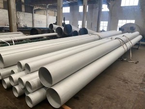
API 5L SEAMLESS & WELDED PIPE
Scope
ANSI / API 5L specifies the manufacture of two product levels (PSL1 and PSL2) of seamless and welded steel pipe for the use of a pipeline in the transportation of petroleum and natural gas. For material use in a sour service application, refer to Annex H; for offshore service application, refer to Annex J of API 5L 45th Edition.
Process
Ingots, blooms, billets, coils or plates used for the manufacture of pipe shall be made via basic oxygen, electric furnace or open hearth in combination with a ladle refining process. For PSL2, the steel shall be killed and melted according to a fine grain practice. Coil or plate used for PSL2 pipe shall not contain any repair welds.
Delivery condition
| PSL |
Delivery Condition |
Pipe grade |
| PSL1 |
As-rolled, normalized, normalizing formed |
A |
| |
As-rolled, normalizing rolled, thermomechanical rolled, thermo-mechanical formed, normalizing formed, normalized, normalized and tempered or if agreed Q&T SMLS only |
B |
| |
As-rolled, normalizing rolled, thermomechanical rolled, thermo-mechanical formed, normalizing formed, normalized, normalized and tempered |
X42, X46, X52, X56, X60, X65, X70 |
| PSL 2 |
As-rolled |
BR, X42R |
| |
Normalizing rolled, normalizing formed, normalized or normalized and tempered |
BN, X42N, X46N, X52N, X56N, X60N |
| |
Quenched and tempered |
BQ, X42Q, X46Q, X56Q, X60Q, X65Q, X70Q, X80Q, X90Q, X100Q |
| |
Thermomechanical rolled or thermomechanical formed |
BM, X42M, X46M, X56M, X60M, X65M, X70M, X80M |
| |
Thermomechanical rolled |
X90M, X100M, X120M |
| |
The suffice (R, N, Q or M) for PSL2 grades, belongs to the steel grade |
|
Chemical requirements
Chemical Composition for PSL 1 pipe with t ≤ 0.984”
| Steel Grade |
Mass fraction, % based on heat and product analyses a,g |
| C |
Mn |
P |
S |
V |
Nb |
Ti |
| max b |
max b |
max |
max |
max |
max |
max |
| Seamless Pipe |
| A |
0.22 |
0.9 |
0.3 |
0.3 |
– |
– |
– |
| B |
0.28 |
1.2 |
0.3 |
0.3 |
c,d |
c,d |
d |
| X42 |
0.28 |
1.3 |
0.3 |
0.3 |
d |
d |
d |
| X46 |
0.28 |
1.4 |
0.3 |
0.3 |
d |
d |
d |
| X52 |
0.28 |
1.4 |
0.3 |
0.3 |
d |
d |
d |
| X56 |
0.28 |
1.4 |
0.3 |
0.3 |
d |
d |
d |
| X60 |
0.28 e |
1.40 e |
0.3 |
0.3 |
f |
f |
f |
| X65 |
0.28 e |
1.40 e |
0.3 |
0.3 |
f |
f |
f |
| X70 |
0.28 e |
1.40 e |
0.3 |
0.3 |
f |
f |
f |
| Welded Pipe |
| A |
0.22 |
0.9 |
0.3 |
0.3 |
– |
– |
– |
| B |
0.26 |
1.2 |
0.3 |
0.3 |
c,d |
c,d |
d |
| X42 |
0.26 |
1.3 |
0.3 |
0.3 |
d |
d |
d |
| X46 |
0.26 |
1.4 |
0.3 |
0.3 |
d |
d |
d |
| X52 |
0.26 |
1.4 |
0.3 |
0.3 |
d |
d |
d |
| X56 |
0.26 |
1.4 |
0.3 |
0.3 |
d |
d |
d |
| X60 |
0.26 e |
1.40 e |
0.3 |
0.3 |
f |
f |
f |
| X65 |
0.26 e |
1.45 e |
0.3 |
0.3 |
f |
f |
f |
| X70 |
0.26e |
1.65 e |
0.3 |
0.3 |
f |
f |
f |
a. Cu ≤ = 0.50% Ni; ≤ 0.50%; Cr ≤ 0.50%; and Mo ≤ 0.15%,
b. For each reduction of 0.01% below the specified max. concentration for carbon, and increase of 0.05% above the specified max. concentration for Mn is permissible, up to a max. of 1.65% for grades ≥ B, but ≤ = X52; up to a max. of 1.75% for grades > X52, but < X70; and up to a maximum of 2.00% for X70.,
c. Unless otherwise agreed NB + V ≤ 0.06%,
d. Nb + V + TI ≤ 0.15%,
e. Unless otherwise agreed.,
f. Unless otherwise agreed, NB + V = Ti ≤ 0.15%,
g. No deliberate addition of B is permitted and the residual B ≤ 0.001% |
Chemical Composition for PSL 2 pipe with t ≤ 0.984”
| Steel Grade |
Mass fraction, % based on heat and product analyses |
Carbon Equiv a |
| C |
Si |
Mn |
P |
S |
V |
Nb |
Ti |
Other |
CE IIW |
CE Pcm |
| max b |
max |
max b |
max |
max |
max |
max |
max |
max |
max |
| Seamless and Welded Pipe |
| BR |
0.24 |
0.4 |
1.2 |
0.025 |
0.015 |
c |
c |
0.04 |
e,l |
0.043 |
0.25 |
| X42R |
0.24 |
0.4 |
1.2 |
0.025 |
0.015 |
0.06 |
0.05 |
0.04 |
e,l |
0.043 |
0.25 |
| BN |
0.24 |
0.4 |
1.2 |
0.025 |
0.015 |
c |
c |
0.04 |
e,l |
0.043 |
0.25 |
| X42N |
0.24 |
0.4 |
1.2 |
0.025 |
0.015 |
0.06 |
0.05 |
0.04 |
e,l |
0.043 |
0.25 |
| X46N |
0.24 |
0.4 |
1.4 |
0.025 |
0.015 |
0.07 |
0.05 |
0.04 |
d,e,l |
0.043 |
0.25 |
| X52N |
0.24 |
0.45 |
1.4 |
0.025 |
0.015 |
0.1 |
0.05 |
0.04 |
d,e,l |
0.043 |
0.25 |
| X56N |
0.24 |
0.45 |
1.4 |
0.025 |
0.015 |
0.10f |
0.05 |
0.04 |
d,e,l |
0.043 |
0.25 |
| X60N |
0.24f |
0.45f |
1.40f |
0.025 |
0.015 |
0.10f |
0.05f |
0.04f |
g,h,l |
As agreed |
| BQ |
0.18 |
0.45 |
1.4 |
0.025 |
0.015 |
0.05 |
0.05 |
0.04 |
e,l |
0.043 |
0.25 |
| X42Q |
0.18 |
0.45 |
1.4 |
0.025 |
0.015 |
0.05 |
0.05 |
0.04 |
e,l |
0.043 |
0.25 |
| X46Q |
0.18 |
0.45 |
1.4 |
0.025 |
0.015 |
0.05 |
0.05 |
0.04 |
e,l |
0.043 |
0.25 |
| X52Q |
0.18 |
0.45 |
1.5 |
0.025 |
0.015 |
0.05 |
0.05 |
0.04 |
e,l |
0.043 |
0.25 |
| X56Q |
0.18 |
0.45f |
1.5 |
0.025 |
0.015 |
0.07 |
0.05 |
0.04 |
e,l |
0.043 |
0.25 |
| X60Q |
0.18f |
0.45f |
1.70f |
0.025 |
0.015 |
g |
g |
g |
h,l |
0.043 |
0.25 |
| X65Q |
0.18f |
0.45f |
1.70f |
0.025 |
0.015 |
g |
g |
g |
h,l |
0.043 |
0.25 |
| X70Q |
0.18f |
0.45f |
1.80f |
0.025 |
0.015 |
g |
g |
g |
h,l |
0.043 |
0.25 |
| X80Q |
0.18f |
0.45f |
1.90f |
0.025 |
0.015 |
g |
g |
g |
i,j |
As agreed |
| X90Q |
0.16f |
0.45f |
1.9 |
0.02 |
0.01 |
g |
g |
g |
j,k |
As agreed |
| X100Q |
0.16f |
0.45f |
1.9 |
0.02 |
0.01 |
g |
g |
g |
j,k |
As agreed |
| Welded Pipe |
| BM |
0.22 |
0.45 |
1.2 |
0.025 |
0.015 |
0.05 |
0.05 |
0.04 |
e,l |
0.043 |
0.25 |
| X42M |
0.22 |
0.45 |
1.3 |
0.025 |
0.015 |
0.05 |
0.05 |
0.04 |
e,l |
0.043 |
0.25 |
| X46M |
0.22 |
0.45 |
1.3 |
0.025 |
0.015 |
0.05 |
0.05 |
0.04 |
e,l |
0.043 |
0.25 |
| X52M |
0.22 |
0.45 |
1.4 |
0.025 |
0.015 |
d |
d |
d |
e,l |
0.043 |
0.25 |
| X56M |
0.22 |
0.45f |
1.4 |
0.025 |
0.015 |
d |
d |
d |
e,l |
0.043 |
0.25 |
| X60M |
0.12f |
0.45f |
1.60f |
0.025 |
0.015 |
g |
g |
g |
h,l |
0.043 |
0.25 |
| X65M |
0.12f |
0.45f |
1.60f |
0.025 |
0.015 |
g |
g |
g |
h,l |
0.043 |
0.25 |
| X70M |
0.12f |
0.45f |
1.70f |
0.025 |
0.015 |
g |
g |
g |
h,l |
0.043 |
0.25 |
| X80M |
0.12f |
0.45f |
1.85f |
0.025 |
0.015 |
g |
g |
g |
i,j |
.043f |
0.25 |
| X90M |
0.1 |
0.55f |
2.10f |
0.02 |
0.01 |
g |
g |
g |
i,j |
– |
0.25 |
| X100M |
0.1 |
0.55f |
2.10f |
0.02 |
0.01 |
g |
g |
g |
i,j |
– |
0.25 |
a. SMLS t>0.787”, CE limits shall be as agreed. The CEIIW limits applied fi C > 0.12% and the CEPcm limits apply if C ≤ 0.12%,
b. For each reduction of 0.01% below the specified max. concentration for carbon, and increase of 0.05% above the specified max. concentration for Mn is permissible, up to a max. of 1.65% for grades ≥ B, but ≤ = X52; up to a max. of 1.75% for grades > X52, but < X70; and up to a maximum of 2.00% for X70.,
c. Unless otherwise agreed Nb = V ≤ 0.06%,
d. Nb = V = Ti ≤ 0.15%,
e. Unless otherwise agreed, Cu ≤ 0.50%; Ni ≤ 0.30% Cr ≤ 0.30% and Mo ≤ 0.15%,
f. Unless otherwise agreed,
g. Unless otherwise agreed, Nb + V + Ti ≤ 0.15%,
h. Unless otherwise agreed, Cu ≤ 0.50% Ni ≤ 0.50% Cr ≤ 0.50% and MO ≤ 0.50%,
i. Unless otherwise agreed, Cu ≤ 0.50% Ni ≤ 1.00% Cr ≤ 0.50% and MO ≤ 0.50%,
j. B ≤ 0.004%,
k. Unless otherwise agreed, Cu ≤ 0.50% Ni ≤ 1.00% Cr ≤ 0.55% and MO ≤ 0.80%,
l. For all PSL 2 pipe grades except those grades with footnotes j noted, the following applies. Unless otherwise agreed no intentional addition of B is permitted and residual B ≤ 0.001% . |
Mechanical properties
| Pipe Grade |
Tensile Properties – Pipe Body of SMLS and Welded Pipes PSL 1 |
Seam of Welded Pipe |
| Yield Strength a |
Tensile Strength a |
Elongation |
Tensile Strength b |
| Rt0,5 PSI Min |
Rm PSI Min |
(in 2in Af % min) |
Rm PSI Min |
| A |
30,500 |
48,600 |
c |
48,600 |
| B |
35,500 |
60,200 |
c |
60,200 |
| X42 |
42,100 |
60,200 |
c |
60,200 |
| X46 |
46,400 |
63,100 |
c |
63,100 |
| X52 |
52,200 |
66,700 |
c |
66,700 |
| X56 |
56,600 |
71,100 |
c |
71,100 |
| X60 |
60,200 |
75,400 |
c |
75,400 |
| X65 |
65,300 |
77,500 |
c |
77,500 |
| X70 |
70,300 |
82,700 |
c |
82,700 |
| a. For intermediate grade, the difference between the specified minimum tensile strength and the specified minimum yield for the pipe body shall be as given for the next higher grade. |
| b. For the intermediate grades, the specified minimum tensile strength for the weld seam shall be the same as determined for the body using foot note a. |
| c. The specified minimum elongation, Af, expressed in percent and rounded to the nearest percent, shall be determined using the following equation: |
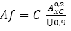 |
| Where C is 1 940 for calculation using Si units and 625 000 for calculation using USC units |
| Axc is the applicable tensile test piece cross-sectional area, expressed in square millimeters (square inches) , as follows |
| – For circular cross-section test pieces, 130mm2 (0.20 in2) for 12.7 mm (0.500 in) and 8.9 mm (.350 in) diameter test pieces; and 65 mm2 (0.10 in2) for 6.4 mm (0.250in) diameter test pieces. |
| – For full-section test pieces, the lesser of a) 485 mm2 (0.75 in2) and b) the cross-sectional area of the test piece, derived using the specified outside diameter and the specified wall thickness of the pipe, rounded to the nearest 10 mm2 (0.10in2) |
| – For strip test pieces, the lesser of a) 485 mm2 (0.75 in2) and b) the cross-sectional area of the test piece, derived using the specified width of the test piece and the specified wall thickness of the pipe, rounded to the nearest 10 mm2 (0.10in2) |
| U is the specified minimum tensile strength, expressed in megapascals (pounds per square inch) |
| Pipe Grade |
Tensile Properties – Pipe Body of SMLS and Welded Pipes PSL 2 |
Seam of Welded Pipe |
| Yield Strength a |
Tensile Strength a |
Ratio a,c |
Elongation |
Tensile Strength d |
| Rt0,5 PSI Min |
Rm PSI Min |
R10,5IRm |
(in 2in) |
Rm (psi) |
| |
|
|
Af % |
|
| Minimum |
Maximum |
Minimum |
Maximum |
Maximum |
Minimum |
Minimum |
| BR, BN,BQ,BM |
35,500 |
65,300 |
60,200 |
95,000 |
0.93 |
f |
60,200 |
| X42,X42R,X2Q,X42M |
42,100 |
71,800 |
60,200 |
95,000 |
0.93 |
f |
60,200 |
| X46N,X46Q,X46M |
46,400 |
76,100 |
63,100 |
95,000 |
0.93 |
f |
63,100 |
| X52N,X52Q,X52M |
52,200 |
76,900 |
66,700 |
110,200 |
0.93 |
f |
66,700 |
| X56N,X56Q,X56M |
56,600 |
79,000 |
71,100 |
110,200 |
0.93 |
f |
71,100 |
| X60N,X60Q,S60M |
60,200 |
81,900 |
75,400 |
110,200 |
0.93 |
f |
75,400 |
| X65Q,X65M |
65,300 |
87,000 |
77,600 |
110,200 |
0.93 |
f |
76,600 |
| X70Q,X65M |
70,300 |
92,100 |
82,700 |
110,200 |
0.93 |
f |
82,700 |
| X80Q,X80M |
80,.500 |
102,300 |
90,600 |
119,700 |
0.93 |
f |
90,600 |
| a. For intermediate grade, refer to the full API5L specification. |
| b. for grades > X90 refer to the full API5L specification. |
| c. This limit applies for pies with D> 12.750 in |
| d. For intermediate grades, the specified minimum tensile strength for the weld seam shall be the same value as was determined for the pipe body using foot a. |
| e. for pipe requiring longitudinal testing, the maximum yield strength shall be ≤ 71,800 psi |
| f. The specified minimum elongation, Af, expressed in percent and rounded to the nearest percent, shall be determined using the following equation: |
|
| Where C is 1 940 for calculation using Si units and 625 000 for calculation using USC units |
| Axc is the applicable tensile test piece cross-sectional area, expressed in square millimeters (square inches) , as follows |
| – For circular cross-section test pieces, 130mm2 (0.20 in2) for 12.7 mm (0.500 in) and 8.9 mm (.350 in) diameter test pieces; and 65 mm2 (0.10 in2) for 6.4 mm (0.250in) diameter test pieces. |
| – For full-section test pieces, the lesser of a) 485 mm2 (0.75 in2) and b) the cross-sectional area of the test piece, derived using the specified outside diameter and the specified wall thickness of the pipe, rounded to the nearest 10 mm2 (0.10in2) |
| – For strip test pieces, the lesser of a) 485 mm2 (0.75 in2) and b) the cross-sectional area of the test piece, derived using the specified width of the test piece and the specified wall thickness of the pipe, rounded to the nearest 10 mm2 (0.10in2) |
| U is the specified minimum tensile strength, expressed in megapascals (pounds per square inch |
| g. Lower values fo R10,5IRm may be specified by agreement |
| h. for grades > x90 refer to the full API5L specification. |
Hydrostatic test
Pipe to withstand a hydrostatic test without leakage through the weld seam or the pipe body. Jointers need not be hydrostatic tested provide the pipe sections used were successfully tested.
Bend test
No cracks shall occur in any portion of the test piece and no opening of the weld shall occur.
Flattening test
Acceptance criteria for flattening test shall be:
- EW pipes D<12.750 in:
- X60 with T 500in. There shall be no opening of the weld before the distance between
- the plates is less than 66% of the original outside diameter. For all grades and wall, 50%.
- For pipe with a D/t > 10, there shall be no opening of the weld before the distance between
- the plates is less than 30% of the original outside diameter.
- For other sizes refer to the full API 5L specification.
CVN impact test for PSL2
Many PSL2 pipe sizes and grades require CVN. Seamless pipe is to be tested in the body.
Welded pipe is to be tested in the body, pipe weld and heat-affected zone.
Refer to the full API 5L specification for the chart of sizes and grades and required absorbed energy values.
Tolerances: Outside diameter, out of roundness and wall thickness
| Specified Outside Diameter D (in) |
Diameter Tolerance, inches d |
Out-of-Roundness Tolerance in |
| Pipe except the end a |
Pipe end a,b,c |
Pipe except the End a |
Pipe End a,b,c |
| SMLS Pipe |
Welded Pipe |
SMLS Pipe |
Welded Pipe |
| < 2.375 |
-0.031 to + 0.016 |
– 0.031 to + 0.016 |
0.048 |
0.036 |
| ≥2.375 to 6.625 |
|
|
0.020D for |
0.015D for |
| +/- 0.0075D |
– 0.016 to + 0.063 |
 |
|
| |
|
By agreement for |
By agreement for |
| |
|
|
|
| >6.625 to 24.000 |
+/- 0.0075D |
+/- 0.0075D, but max of 0.125 |
+/- 0.005D, but max of 0.063 |
0.020D |
0.015D |
| >24 to 56 |
+/- 0.01D |
+/- 0.005D but max of 0.160 |
+/- 0.079 |
+/- 0.063 |
0.015D for but max of 0.060 |
0.01D for but max of 0.500 |
| For |
For |
| |
|
| By agreement |
By agreement |
| for |
for |
| |
|
| >56 |
As agreed |
| a. The pipe end includes a length of 4 in ate each of the pipe extremities |
| b. For SMLS pipe the tolerance apply for t≤0.984in and the tolerances for the thicker pipe shall be as agreed |
| c. For expanded pipe with D≥8.625in and for non-expanded pipe, the diameter tolerance and the out-of-roundness tolerance may be determined using the calculated inside diameter or measured inside diameter rather than the specified OD. |
| d. For determining compliance to diameter tolerance, the pipe diameter is defined as the circumference of the pipe in any circumferential plane divide by Pi. |
| Wall thickness |
Tolerances a |
| t inches |
inches |
| SMLS pipe b |
| ≤ 0.157 |
-1.2 |
| > 0.157 to < 0.948 |
+ 0.150t / – 0.125t |
| ≥ 0.984 |
+ 0.146 or + 0.1t, whichever is the greater |
| – 0.120 or – 0.1t, whichever is the greater |
| Welded pipe c,d |
| ≤ 0.197 |
+/- 0.020 |
| > 0.197 to < 0.591 |
+/- 0.1t |
| ≥ 0.591 |
+/- 0.060 |
| a. If the purchase order specifies a minus tolerance for wall thickness smaller than the applicable value given in this table, the plus tolerance for wall thickness shall be increased by an amount sufficient to maintain the applicable tolerance range. |
| b. For pipe with D≥ 14.000 in and t≥0.984in, the wall thickness tolerance locally may exceed the plus tolerance for wall thickness by an additional 0.05t provided that the plus tolerance for mass is not exceeded. |
| c. The plus tolerance for wall thickens does not apply to the weld area |
| d. See the full API5L spec for full details |